What if you need to know the voltage value of your supply?
Ok you say. Fine, I'll just measure it with the ADC.
The trouble is you get the same reading of 1023 whatever the supply is set to!
The ADC is ratiometric - it's not an absolute measurement as it
uses the power supply as a reference. You need to use a separate
accurate voltage source as a reference to find out an absolute voltage
measurement.
There are two things you can do:
1. Supply an external - accurate - voltage to Aref.
2. Use the internal bandgap 1V1 voltage reference.
The internal bandgap is not without a problem - its initial accuracy is ±9%!
Find out here how to calibrate it, and use it to measure your power supply voltage.
The Arduino Voltage Reference (1.1V) is built into some Arduino
microcontrollers. The Uno and the Nano both have one, and quite a few of
the other Arduinos have them.
This page:
Shows you how to measure the "real" value of Vcc (using the 1V1 reference).
Attempts to quantify the internal voltage reference (how good is it?).
The first item above is interesting; when you use the 1V1 internal
voltage reference as a reference to the ADC you can only measure
voltages up to 1V1 but in this document you can find out how to
"calibrate" the supply voltage.
This is an unusual technique where you use the supply as a reference
and measure the 1V1 voltage. If you have previously calibrated the 1V1
reference (to get rid of the 10% error) then your measurement of the
supply voltage will be as accurate as the calibration of the 1V1
reference!
The advantage is that you can now measure the complete supply range -
using the calibrated supply voltage. The disadvantage is that you need
to re-measure the supply voltage to account for variations over
time/temperature changes.
Note: Of course, you could add
an external voltage divider to bring the measured voltage into the range
of 1V1, but this technique saves those components.
Note: Although the Internal Arduino Voltage Reference is stable with
temperature and voltage, its initial value varies between chips
(probably due to differences in chip manufacture). You need to calibrate it (see this page).
The Arduino voltage reference is useful when you don't want to go to
the trouble of adding an
external
chip to figure out voltages and need a more stable reference than Vcc or
where the supply voltage changes (and you also don't want to add a
voltage divider).
For instance the Arduino Uno/Nano can operate from 1V8 to 5V5 and using two AA
cells would allow operation (but only if you set the clock to 4MHz - see
the datasheet section 29.3 "Speed Grades"). You can use the internal voltage reference to monitor
the state of the battery - with no extra components.
Bandgap Voltage Reference
The type of reference in the ATMega328P is a bandgap type. This uses
two elements, one with the negative temperature coefficient and
one with a positive temperature coefficient which cancel out
temperature effects.
While not
giving you ultra precise voltage readings in the Arduino, the circuit is designed to be stable against changes in
temperature and supply voltage.
This type of circuit layout is used in state of the art references e.g. MAX6143.
However, in the ATMega328 and similar, the process to control the layout
of the chip on silicon is not as well defined and does not use laser
trimming, hence the poor initial accuracy of the Arduino voltage
reference (±9%).
You can find out how to eliminate this offset later in this page.
Note: If you use an external reference the ADC
measurement will be more accurate since you control the chip specification.
However, remember the
internal ADC in the Arduino is not too accurate: Absolute
accuracy 2LSB (including INL, DNL, quantization, gain and offset errors).
Warning: Never use an external
voltage reference and at the same time enable the internal reference - you may get magic smoke!
Uses for the Arduino Voltage Reference
The Arduino voltage reference can be used in one of five different ways:
For brown-out detection (See datasheet to enable).
As a measurement value in the ADC (fed in to one of the inputs).
As the reference for ADC measurements.
As an input to the comparator.
Temperature measurement (The ADC must use the internal reference).
Brown out detection
Brown-out detection allows the processor to identify when the supply
voltage has dipped below a threshold but has not completely gone to
zero. This is used to flag to the processor that memory may have been
written badly. It just provides an extra layer of reliability to an
application.
An input to the ADC
Measuring the reference at an ADC input would allow calibration of a
different reference source e.g. the supply (see here) or as a crude comparison to
other ADC inputs (unless you calibrate the reference first as shown in
this page - in which case it could be quite accurate (~1%)).
ADC reference
Using the Arduino voltage reference as you would expect it to be used!
TIP: Using the 1V1 reference means the 10 bit ADC has an LSB value
of ~1mV (1.074mV/LSB). However, you can then only measure voltages up to 1.1V!
Comparator input
Using the voltage reference allows crude comparison i.e you can only
compare any input voltage to 1V1. One interesting point is that any of
the ADC inputs can be compared by the comparator - and that is without
using any more external components. See section 23.2 of the datasheet
labelled "Analog Comparator Multiplexed Input".
You could ask the question "Why bother using the comparator when you can
easily calculate the result using the ADC?" The answer is speed.
The comparator can compare two voltages within 100s of nanoseconds
whereas the ADC is a successive approximation type and takes about 13us
to gather the ADC value. This value has to be retrieved by the processor
and then you would compare the value to a limit setting, taking far
more time.
Temperature Measurement
Since the Arduino voltage reference is independent of temperature it can
be compared to the output of a temperature dependent circuit - a
circuit inside the chip. This allows you to measure temperature in the
ATMega328P.
The temperature
sensing element in the ADC can be set to one of the ADC inputs. The
datasheet states that the temperature coefficient is 1mV/ºC but that
the initial accuracy is ±10ºC due to process variation in chip
manufacture. (See section 24.8 of the datasheet labelled "Temperature
Measurement"). To get an accurate reading requires calibration of this
system.
How to Measure the Supply Voltage
You can operate the microcontroller (ATMega328p - Uno, Nano) from
between 1V8 and 5V5. The
microcontroller can not detect this "real" value of the supply voltage
this unless you use a known reference
voltage to figure it out. This is because the ADC measures everything
relative to a reference i.e. the supply voltage is the reference!
Warning: At VCC=4.5V clock can be 20MHz and at VCC=2.7V the clock speed must be <= 10MHz, and for VCC=1.8V
the clock speed must be <= 4MHz). See section "29.3 Speed Grades"
which shows that the clock frequency must be linearly reduced with
decreasing supply voltage.
This method is a sort-of reverse method of ADC measurement.
Instead of using the voltage reference you use the
supply voltage as the reference and the "Arduino internal voltage
reference" as the quantity to be measured!
Since you know that the bandgap reference is 1.1V then you can figure
out the supply voltage value by doing a simple bit of maths (below).
...to your measured value. The representation of 1.1V is 11000 which
is a fixed decimal point representation where the decimal point is
assumed to be one place to the right. So you can think of 11000
representing the number of 0.1mVs in the actual voltage i.e. 11000 x
0.1e-3 = 1.1V
Using an ADS1115 or good voltmeter will give you enough digits. If
you use a standard DVM then you will only get 3 digits (on a 2 volt range) so set the
last two digits to zero.
////////////////////////////////////////////////////////////////
voidselfMeasureVcc(char*buf){
uint8_tlow,high;// ADC bytes.
// Default reference value. Set this to your measured reference voltage (or leave as is).
// The value uses an integer fixed point representation
// with the assumed decimal point one place to the right.
staticunsignedlongarduinoADCcal=11000;
if(strlen(buf)>1){
if(strlen(buf)<6)
Serial.print(F("Not enough digits"));
elseif(strlen(buf)>6)
Serial.print(F("Too many digits"));
else
arduinoADCcal=atoi(&buf[1]);}elseif(strlen(buf)==1)
Serial.print(F("Ref calibration value: "));Serial.println(arduinoADCcal);
// ADCSRA |= _BV(ADEN); // Enable ADC. Enabled by init() in Arduino code.
ADMUX=_BV(REFS0)|_BV(MUX3)|_BV(MUX2)|_BV(MUX1);// Set VCC ref and band gap as input.
delay(2);// Vref settling time delay
// Throw away 1st result as datasheet says
// After switch, ref may be invalid.
// Datasheet: "24.5.2 ADC Voltage Reference".
ADCSRA|=_BV(ADSC);// Start conversion
while(bit_is_set(ADCSRA,ADSC));// Wait for conversion complete.
ADCSRA|=_BV(ADSC);// Start conversion
while(bit_is_set(ADCSRA,ADSC));// Wait for conversion complete.
// ADCL must be read first, then ADCH, to ensure that the content
// of the Data Registers belongs to the same conversion
// Datasheet Section "24.2 Overview"
low=ADCL;// Read ADCL first which blocks ADCH updates.
high=ADCH;// After reading ADCH both registers can be updated by the chip.
longADCValue=(high<<8)|low;
Serial.print(F("ADC value of 1V1 ref: "));Serial.println(ADCValue);
#define BINS 1024L // VCC/1024 is the value of each LSB of the ADC.
Serial.println((arduinoADCcal)*BINS);
Serial.println(((arduinoADCcal*BINS)+5L));
Serial.println(((arduinoADCcal*BINS)+5L)/10L);
// Note +5 = middle of LSB bin
// Calculate Vcc (in mV); 1125300 = 1.1*1024*1000
// Here ccal value is 1.1*10e4 so no need for *1000 and must divide by 10.
uint32_tres=(((arduinoADCcal*BINS)+5L)/10L)/ADCValue;
// Calculate Vcc (in mV); 1126400 = 1.1*1024*1000
// should be 1024 / ADCValue = 1125300L / ADCValue; // Calculate Vcc (in mV); 1125300 = 1.1*1023*1000
// internal1.1Ref = 1.1 * Vcc1 (per voltmeter) / Vcc2 (per readVcc() function)
Serial.print(F("Measured (mV) "));Serial.print(res);Serial.println(F(" mV"));}
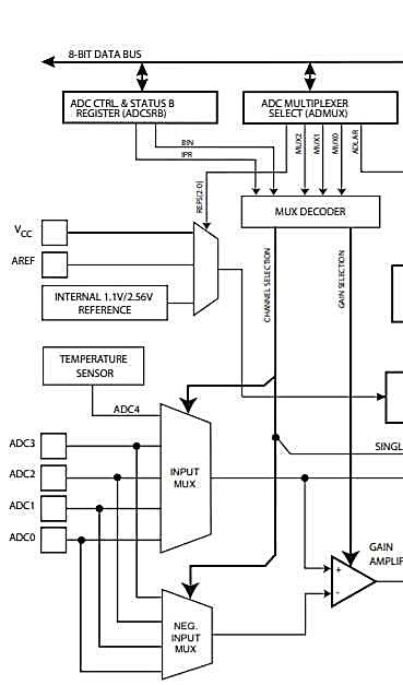
Arduino Voltage Reference Block Diagrams
Arduino Uno/Nano ADC Mux block diagram
Source: ATMega328P datasheet
Arduino ATtiny85 ADC Mux block diagram
Source: ATtiny85 datasheet
ATTiny85 Internal Voltage Reference
The ATTiny85 voltage reference, which is selectable as either 1V1 or 2.56V, is slightly differently arranged in the ADC. The AREF pin can only be set up as an input (there is no switching FET that connects the internal reference mux to the AREF pin). So you cannot setup the Arduino voltage reference for measurement at the AREF pin.
Therefore you can't calibrate it directly. You would either assume that
it has the stated value or accurately measure the Vcc supply then take
an ADC reading (but remember the ADC has its own errors as well!).
One way that would eliminate ADC errors is to feed in a variable voltage
to an ADC input - which you measure. Then compare it to the reading
from the voltage reference (ADC reading). Once the two readings match
the input voltage would then reveal the true Arduino reference voltage
(of course only to 1LSB accuracy).
TIP: Increase an ADC bit resolution by oversampling.
Calibrating the Arduino Voltage Reference
To calibrate the reference in an Uno or Nano you just turn on the
reference and measure the voltage at the reference pin. Remember the
only thing on the pin should be a capacitor and no other driving
circuitry (if you want to preserve the chip!).
Warning: Do not connect any other voltage reference to the VREF
pin when switching the Arduino (Uno/Nano) voltage reference on - there is no
protection and you could damage either the external reference or the
internal reference circuit.
Turning on the reference is quite simply using the following Arduino code:
analogReference(INTERNAL);
However, you will need to activate the ADC to enable the reference, so a simple read will do.
analogRead(0); // Could be any channel
This is due to the way the "wiring" code is written - the mux registers
and REFS0/1 are only written just before an ADC read command (within the analogRead() function).
For the arduino Mega you can choose between the following:
INTERNAL1V1
INTERNAL2V56
Place the above code in the setup() part of the Arduino Sketch.
Warning: Ensure NO voltage is applied to the Vref pin before this test.
If you are going to use the internal reference then there should not be
an voltage applied, but if using a circuit from somewhere else
there could be an external reference of voltage divider attached.
TIP: Attach a 100nF capacitor to the Vref pin for noise reduction.
Now connect a multimeter to the VREF pin and write down the result (for use in your code - see measuring the supply voltage, specifically).
TIP: Use a standard multimeter, or for more digits use
an ADS1115 in differential mode or a Fluke meter (very expensive).
To set the reference back to the supply use:
analogReference(DEFAULT);
...again followed by...
analogRead(0); // Could be any channel
Code for analogue operation is found here:
"C:/Program Files (x86)/Arduino/hardware/arduino/avr/cores/arduino/wiring_analog.c"
Definitions (#define ) are here:
C:/Program Files (x86)/Arduino/hardware/arduino/avr/cores/arduino/Arduino.h
The Arduino code above ( for internal reference selection ) will set the
registers as follows (datasheet section: 24.9.1 ADMUX ADC Multiplexer
Selection Register):
ADMUX bits 7 and 6 set high (REFS1 and REFS0).
ADMUX bits 3..0 set to B1110.
Note: The data sheet states:
"The first ADC conversion result after switching reference voltage
source may be inaccurate, and the user is advised to discard this
result."
(See datasheet section "24.5.2 ADC Voltage Reference").
So you should throw away the first ADC result.
Arduino Voltage Reference Performance
The information in the datasheet on the Arduino voltage reference states that it has maximum and minimum values of
1.0V ~ 1.2V, and nominally 1V1. Other than this there is no more information at all.
There is no information about repeatability or stability. It suggests that the voltage could vary by ±9% around 1.1V.
So the real question is:
Is the Arduino voltage reference any good at
all?
The specification seems to imply that it might vary ±9% at any time.
In fact this is not true and the voltage reference is far better, and
quite useful.
On this page there are some voltage reference measurements - these
are not exhaustive but will give you a flavour of the bandgap
reference performance.
Arduino voltage reference Questions
Questions asked here are:
How does the reference voltage change with temperature?
How does the reference voltage change with Vcc?
How stable is the reference voltage in general?
Remember these measurements are based on testing a few chips
and one or two sets of measurements. They will therefore give an
impression and not the absolute answer.
Note: All voltage measurements were made using an ADS1115 on a breakout
board. All voltage measurements were made in ADS1115 differential mode.
Temperature measurements were made using an MAX6675 and type J
thermocouple.
Initial Accuracy
The initial accuracy is bad at ±9% but calibrating the Arduino voltage reference allows you to eliminate this error.
Note: The MAX6143 has an initial accuracy of 0.05% (180 times better c.f. 9%).
Output Stability
Two boards are measured, the first is s standard Arduino uno board and
the second is an Arduino Nano board. These both use the same processor
ATMega328P.
Measurements made on different time/days of an Arduino Uno powered from the USB (hub) power supply gave the following results:
Arduino Uno USB Stability Measurements
Arduino Uno (PDIP)
USB (HUB) Power Supply
Voltage (Ambient temp)
% error (5V)
Internal
Reference
% error (1V1)
4.806V (21ºC) Diff
3.9%
1.104V Diff
0.36%
4.826V (16ºC) Diff
3.5%
1.097V Diff
0.27%
4.862V (22ºC) Diff
2.8%
1.0976V Diff
0.22%
4.878V (21ºC) Diff
2.4%
1.0980V Diff
0.18%
4.842V (20ºC) Diff
3.2%
1.0975V Diff
0.23%
4.809V (19.5ºC) Diff
3.8%
1.0963V Diff
0.34%
4.788V (23ºC) Diff
4.2%
1.0957V Diff
0.39%
4.866V (23ºC) Diff
2.8%
1.0956V Diff
0.39%
4.853V (20ºC) Diff
17/2/20
2.9%
1.0958V Diff
0.38%
4.876V (17ºC) Diff
18/2/20
2.5%
1.0961V Diff
0.35%
4.860V (18ºC) Diff 24/2/20
2.8%
1.0957V Diff
0.39%
Max error change for Vcc = 4.2 - 2.4 = 1.80 %
Max error change for Vref = 0.39 - 0.18 = 0.21%
Measurements made on different time/days of an Arduino Nano powered from a PC USB port gave the following results:
Arduino Nano USB Stability Measurements
Arduino Nano (MSOP)
USB (PC) Power Supply
Voltage (Ambient temp)
% error (5V)
Internal
Reference
% error (1V1)
4.821V (20ºC)
3.6%
1.070V
2.72%
4.824V (16ºC)
3.5%
1.069V
2.81%
4.831V (17ºC) Diff
3.4%
1.068V Diff
2.91%
4.825V (22ºC) Diff
3.5%
1.068V Diff
2.91%
4.851V (21ºC) Diff
3.0%
1.068V Diff
2.91%
4.852V (15ºC) Diff
3.0%
1.069V Diff
2.81%
4.830V (23ºC) Diff
3.4%
1.067V Diff
3.00%
4.833V (20ºC) Diff
17/2/20
3.3%
1.067V Diff
3.00%
4.862V (17ºC) Diff
19/2/20
2.8%
1.0691V Diff
2.81%
4.879V (20ºC) Diff 21/2/20
2.4%
1.0715V Diff
2.69%
Max error change for Vcc = 3.6 - 2.4 = 1.20 %
Max error change for Vref = 3.00 - 2.69 = 0.31%
The USB voltage varies by 2.4% to 3.6% and this does not have a big
effect on the error variation in the reference (See voltage measurements
below).
Notice how the reference voltage remains constant i.e. has a constant
offset error. Even though the voltage reference starts off from a value of
1.070V it keeps close to that value. This is probably due to the
manufacturing process and seems to remain constant over time.
For the top set of results, the supply is
taken from a USB hub with its own power output while for the bottom it
is a direct PC USB output. The latter seems a little more stable (Nano).
In both cases using the on board internal voltage reference
will give a more consistent result as it will have tighter voltage regulation.
Note: Remember you are either using the 5V USB supply directly (when
working on the bench) or using an external power block. The on board 5V regulator - LD1117AG (same as NCP1117) - has a
tighter error spec (0.1V in 5V = 2%) than USB power (see supply sensitivity measurements below).
Conclusion on Stability
Even though the Arduino voltage reference has an initial offset error
(probably due to the manufacturing process) the stability of the
reference remains very good. with measurements here showing between
0.21% ~ 0.31% change.
Voltage Supply Stability
Using an ATMega382p on a solderless breadboard and connected to a variable supply voltage.
Supply Stability Measurements
Supply Voltage
Internal
Reference
% Initial error
change(1V1).
5.261V (20ºC) Diff
1.0995V Diff
0.05%
4.948V (20ºC) Diff
1.0988V Diff
0.11%
4.389V (20ºC) Diff
1.0980V Diff
0.18%
4.056V (20ºC) Diff
1.0975V Diff
0.23%
3.615V (20ºC) Diff
1.0971V Diff
0.26%
3.370V (20ºC) Diff
1.0968V Diff
0.29%
2.759V (20ºC) Diff
1.0965V Diff
0.32%
Note: The reference produced odd values at 2.3V so
they are not included. The reason is that the maximum clock speed
allowed is proportional to the supply voltage - should lower clock speed
to 4MHz for operation at 1V8 (See datasheet section 29.3 Speed Grades -
safe operating area).
The error changes by -1.2mV per Supply volt drop when starting from from 5.26V. This is -.11% per supply volt drop.
The bandgap voltage reference seems quite good, being insensitive to
supply voltage changes. It drops by 1.2mV per supply volt drop starting
at 0.05% error at 5.26V supply. If the supply is held constant then this
offset error can also be eliminated by calibrating the reference.
Temperature Stability
Using a thermocouple (type J) with the MAX6675 chip and the MSOP Arduino
Nano. Heating the chip for a minute and waiting until the temperature
stabilised. The MAX6675 thermocouple has an offset temperature error but
what we really want is the change in temperature
and how that relates to the reference output. The ambient temperature
is also measured using a different device to give a reference point for
the thermocouple.
Arduino Nano Temperature Measurements
For the Nano ambient temperature measured by the thermocouple is 24.5ºC
(original thermometer says 23ºC) so quite close. Chip temperature is
30ºC.
1st measurement:
Vref is 1.0674V.
Vref is 1.0659kV heated chip to 75ºC
Drop is : -1.5mV
Change over temperature
For a 35ºC temperature change the reference voltage changes by -1.5mV.
roughly -1.5/35 = -0.043mV/ºC. However this is based only on one device
and one measurement!
Change is -0.043mv/ºC
For a temperature increase from 25ºC to 125ºC (100ºC delta) the reference
should drop by 4.28mV. In percentage terms that is (4.28e-3/1.1)*100 =
0.39%.
For a temperature decrease from 25ºC to -40ºC (-65ºC delta) the reference
should increase by 2.79mV. In percentage terms that is (2.79e-3/1.1)*65 =
0.16%.
If you consider a simple transistor that has a -2.1mV/ºC temperature
change then for the same temperature delta you would get a 201mV voltage
change (18.2% change) so the bandgap circuit is doing quite well!
2nd measurement:
Vref is 1.0665V.Temp 30ºC
Vref is 1.0652kV heated chip to 75ºC
Drop is : -1.3mV - So this is a similar result to the first one.
3rd measurement:
Vref is 1.0688V.Temp 30ºC
Vref is 1.0683kV heated chip to 75ºC
Drop is : -0.5mV - A little different, but in the same range.
Conclusion on Temperature
The temperature performance is good with only 0.55% reference
change over the full temperature range (estimated from 35ºC to 75ºC
results).
The reference voltage changes by 0.003% per ºC (estimated) [ 0.55%/165 (estimated) ].
Note: The MAX6143 has 1000 times better temperature performance at 3ppm/ºC.
Over the full temperature range (-40ºC to +125ºC) the reference will
change by about 0.55% (0.39% + 0.16%) = 0.55% (from 1V1) which is not too bad.
The voltage reference should change by +2.79mV ~ -4.28mV (from 1V1) over these temperatures.
Conclusions on the Arduino Voltage Reference
It is possible to use the internal bandgap reference (1V1) to measure
the supply voltage of your microcontroller. As long as you calibrate it
first it can be accurate even with changes to temperature and supply
voltage.
This makes it useful in monitoring the supply voltage especially in
battery supplied systems where it is important to display to the user
when the battery is going to run out!
The reference can have a large offset (due to the manufacturing
process) ±9% so its initial accuracy can be bad. You can eliminate this
by calibrating it with an accurate voltage measurement.
Supply voltage sensitivity: ~-1.2mV per Supply volt drop.
This is ~-.11% per supply volt drop.
Temperature stability: ~0.003% per ºC (estimated)
~0.55% over the full temperature range.
Output voltage stability: ~0.31%
To get the best results from the Arduino voltage reference you should
calibrate it (just measure the voltage reference with a multimeter or
ADS1115 chip. This will then eliminate offset voltages due to
manufacturing process and supply volt sensitivity (if the voltage source
remains constant i.e. supplied through a regulator).
This will then give a stability of 0.55+0.31 = ~0.86%.
Remember this is an estimate based on very few samples, so your
results may vary, but it does show that the reference can be made more
stable if calibrated. It also shows that the Arduino voltage reference
may be more useful than you imagined.
Written by John Main who has a degree in Electronic Engineering.
Unlock the secrets of Arduino scrolling displays! This beginner-friendly guide shows you how to create real-time, dynamic graphics using an SSD1306 OLED, perfect for tracking sensor data and building…


Comments
Have your say about what you just read! Leave me a comment in the box below.
Don’t see the comments box? Log in to your Facebook account, give Facebook consent, then return to this page and refresh it.