Digital I/O Expansion
How to expand your interfaces using digital I/O serial techniques.
You are probably here because you have run out of I/O pins. Prossibly:
- Maybe you only have one pin left unused and need to add a few more functions.
- The I/O you need is far more than the number of pins available on your microcontroller.
- You need a high speed parallel port but have one less than the needed parallel pins available.
- You need to add hundreds of temperature sensors and want to use only one microcontroller.
- You really don't want to route tons of new wires on an existing design.
Using One-Wire, SPI or I2C devices can solve these problems.
The way to add more functions to a pin limited system is to use serial communication. As long as you have at least one pin available all is not lost.
There are several methods and each has different tradeoffs. Here is a list of possible methods, in order of the number of pins needed (excluding ground), but not in any other particular order of importance.
| Type | Wires |
|---|---|
| Jump to Section SPI | 3-4 |
| Jump to section: I2C | 2 |
| Jump to section: Dallas 1 wire | 1 |
| Jump to section: Serial to parallel | 3 |
| Jump to section: Parallel to serial | 3 |
| Jump to section: Johnson counter | 2 |
| Jump to section: RS232 | 1 |
Digital I/O expansion: Dallas 1 wire
This is a proprietary communication system created by Dallas Semiconductor (part of Maxim www.maxim-ic.com). Each device has a unique laser engraved address etched into it so that you can put multiple devices on the same wire network.It uses a single I/O pin (working as abus master) to control all slave devices attached to that I/O pin and all of the devices can be powered by the I/O pin! and the devices can be daisy chained over 10s of metres.
Typical devices you can use include:
| Device | Description |
|---|---|
| DS18B20 | A popular thermometer (very accurate) |
| DS2408 | 8 channel addressable switch; input and output & latch. |
| DS2413 | A switch (turns on and off an open drain transistor 28V max). |
| DS2433 | 4k bit EEPROM |
| DS2450 | Quad ADC converter |
| DS2423 | Counter with 4kbit RAM |
| DS28E04-100 | 4kbit EEPROM and dual IO |
| DS2417 | Real Time Clock |
| DS2890 | Digital POT |
Note this is not the full list - there are lots more devices!
Although you might think that the 1 wire system is only for long distance control and measurement you can use it within a single board and you can use 100s of devices on the same wire network.
There is more information on how to use it in the DS18B20 project which also discusses parasitic mode and how to ensure the network does not go down when too much power is demanded from lots of devices.
Digital I/O expansion: Johnson counter
One chip I like to use for very simple I/O expansion is the 74HC4017 original the CMOS version but also available in HCT etc. It is a Johnson counter that sequentially turns on one of 10 outputs. All you need to drive it is two controls reset and clock. It does not have a lot of output current drive so you may need transistors to provide more current.Its is a useful chip for multiplexing seven segment displays.
The frequency counter project here uses the 4017 to sequentially
skip through each of 8 digits for an 8x Seven segment display.
Digital I/O expansion: Serial to parallel/parallel to serial chips
You can use the discrete chips 74HC595 (serial in and 8 bit parallel out) and 75HC165 (8 bit parallel in and serial out). All you need for each type is 3 controls:- Latch (to get or set stable data).
- Reset.
- Clock.
This separates the output signals (595) from the shift register so you can setup all the serial data, clocking it into the device without changing the outputs. When you are ready you latch the data through to the output using the latch control signal.
This ensures that the data never changes until you are ready for it to change and a similar operation happens for the parallel to serial device.
Note: You can easily cascade these devices to provide more I/O using the same set of controls.
You can find more information on the 595 here.
Digital I/O expansion: I2C
This is one of the more flexible ways of interfacing using only two pins and the most important point is that it gives data transmission in both directions to/from slave devices. The SPI protocol does this in a more limited way.You can add devices onto the bus limited by the addressing scheme ~120 devices and the capacitance that each device adds to the total capacitance. Addresses are fixed for manufacturers and device family and some have extra pins to set the lower address range e.g. for extra serial EEPROMS of the same type.
For more information on I2C click here.
| I2C Device | Description |
|---|---|
| PCF8574 | 8-bit I/O port (cheap version JLC1562). |
| MCP23017 | 16 bit configurable I/O with interrupts. |
| MAX1036 | Quad ADC converter 8bit. |
| PCF8591 | Quad ADC and 1 DAC 8bit. |
| MAX5548 | DAC 8bit. |
| SSD1306 | I2C or SPI OLED Display |
| DS1672 | 32-Bit Binary Counter RTC. |
| DS1803 | Dual Digital POT (256 position). |
| DS1307 | Real Time Clock. |
| DS1624 | Digital thermometer and memory. |
| BMP280 | Digital Barometer (is configurable as SPI). |
Note: There are many more I2C devices!
Digital I/O expansion: SPI
This is the Serial Peripheral Interface using 4 wires (3 if data is only sent in one direction). It is basically a shift register based protocol - (because of this it can run fast). For more information on SPI click here.| SPI Device | Description |
|---|---|
| MCP23S17 | 16 bit configurable I/O with interrupts. |
| MAX7219 | 64 LED driver (cascadable). |
| MAX7317 | 10-bit I/O expander (26MHz!). |
| MAX1062 | Quad ADC converter 14bit. |
| MAX5590 | DAC 8 channel 10bit |
| SSD1306 | I2C or SPI OLED Display |
| AD8402 | Dual Digital POT 256 position. |
| DS1307 | Real Time Clock. |
| MAX6627 | 12 bit temperature sensor. |
| BMP280 | Digital Barometer (is configurable as I2C). |
Note: There are many more SPI devices!
Digital I/O expansion: RS232
Perhaps the most unusual one is the RS232 serial comms method since a lot of microcontrollers have a built in serial module you can use it as a simple asynchronous data transfer system i.e. chuck data from one microcontroller to another (or boith ways if you want).For one way communication you only need one wire - serial output (from the
transmitting micro) to serial input (to the receiving micro). You won't need
a level translator if you just communicate between two chips on the same board
and because it will be over a short distance you can run it fast..
The best way to use it is with the built in UART in each microcontroller but
you could use a software version if absolutely necessary.
You can find more information by clicking the following links for RS232 and usage.
I/O port expansion : Summary and a look at speed issues
The SPI interface is the fastest (>10MHz) but uses the most pins while an I2C interface is medium speed (100kHz-400kHz) - although there is a faster MHz mode - and RS232 is the slowest. RS232 uses two pins for communication in both directions but if you need only transmit data to a peripheral then you can use one pin.Digital I/O expander : speed
| Interface | PINS required | Can create in software | Speed |
|---|---|---|---|
| SPITM | 3-4 (and ground) | Yes (slower) | >10MHz |
| I2CTM | 2 (and ground) | Yes (slower) | 100kHz/ |
| RS232 | 1 (and ground) (for simplex). | Yes (slower) | 50kHz |
| One-WireTM | 1 (and ground) (for dual simplex) | Yes (slow anyway) | ~100 Hz |
SPI Example Project:
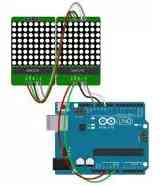
 This is an example
ArduinoTM Project that uses a 4 wire SPI device (MAX7219) for digital I/O (actually in this case just for output)
adding 64 LED outputs. In addition you can cascade multiple MAX7219 devcies for
unlimited I/O.
 In practice the maximum number of devices speed will depend on how fast the SPI interface goes and the rate of LED output change required.
For a massive display the processor will need to be faster - to work out which pixels to change and when etc. For a (5 - 10 ) x 64 LED display there is no problem.
One-WireTM Example Project:
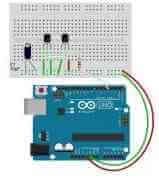
 This is an
example ArduinoTM Project that uses the One_wireTM
protocol (one wire plus a ground return line - so really 2 wires - but still
very impressive). It also runs on long wires(10's of
metres) - you could run a wire pair into the garden to record temperature using
no power supply!
This is a DS18B20 thermometer accurate to about 0.5°C over a wide temperature range.
The devices can be run either from an extra power line or in parasitic mode where the power is leeched of a data line i.e. you only need a micrcocontroller I/O pin to supply power and control it.
Site Map | Terms of Use


Comments
Have your say about what you just read! Leave me a comment in the box below.
Don’t see the comments box? Log in to your Facebook account, give Facebook consent, then return to this page and refresh it.