- Home
- Arduino Interfaces
- Logic Level Converter
Logic Level Converter: How to interface two different voltage
systems using only two resistors and a MOSFET. It implements a
bi-directional interface that uses a subtle MOSFET property to make it
all work.
This page is all about logic level converters which allow you to
easily
change between different logic voltage levels. You will often want to do
this to interface your 3V3 sensor to your 5V Arduino. Or perhaps you
are using an EP32 that only works with 3V3 and you need to interface a
5V sensor or display.
The logic level converter is a very useful circuit because it allows
true "bi-directional" communication which is a very unusual property
that you do not find in most circuits - most are output only, or input
only. It's true you can create multiple digital transmission gates to achieve a bi-directional microcontroller pin, but the logic level converter uses a single MOSFET to achieve this operation.
You know when you just bought that nice shiny new chip to play with, you get it in the post and only then do you think: What about voltage levels? Then you see that the new chip only works at 3V3 and the only microcontroller you have works at 5V! See this project for an example of using the logic converter circuit.
Logic Level Converter using resistors
First of all you think that's easy, I'll just use a voltage divider to drop the high side voltage to 3V3 and
problem solved. Maybe it is, but if your device is an I2C device (where you need
bidirectional communication on the data line), using a divider on the high side
won't allow the voltage to go the other way at a reliable level.
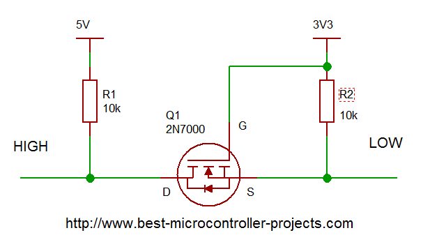
The solution is to use a level converter which only requires a MOSFET, and two pull up resistors.
This method uses a MOSFET and relies on the parasitic diode between
Source and Drain (this is usually a problem rather than a benefit!), to
allow full bidirectional communication with low and high side voltages.
The operation is explained below.
Logic Level Converter using MOSFET
This is a very useful bit of electronics that also happens to be extremely simple, but extremely clever. It lets you easily convert between different voltage level systems using only a simple enhancement mode logic level MOSFET and a couple of 10k resistors.
Since the 10k resistors pull up inactive lines, they have to charge
any stray capacitance so for fast speed use 1k resistors. The rate of
voltage rise will therefore be faster.
MOSFET Level converter diagram
2N7000 pinout


Logic Level Converter Operation
wrt = with respect to.
High side '1'
When the high side outputs a '1' (5V) drain and source are pulled towards
the high voltage so the source is high wrt. gate (reverse Vgs voltage) so the
MOSFET is off so the low side pullup is active and pulls the low side to
3V3.
High side '0'
When the high side outputs a '0' (0V) the source is pulled low wrt gate, so the gate is higher than the source and the MOSFET is on (Vgs is positive). The MOSFET then conducts the zero through to the low side pulling down the low side.
Low side '1'
When the low side outputs a '1' (3V3) the gate source voltage is zero so the
MOSFET is off. The high side pullup is active and pulls the high side to 5V.
Low side '0'
When the low side outputs a '0' (0V) the gate source voltage is 3V3 and the MOSFET is on. The MOSFET then conducts the 0V through to the high side pulling down the high side.
Level converters and SPI
For a 4 wire SPI interface there is no bidirectional requirement (data out:
SDO, and data in: SDI use separate pins) so you could use the divider method
and that requires 3 dividers with a total of 6 resistors.
To go from 5V to 3V needs a resistive divider with 22k and 33k (which drops the output to 3V) (or you can replace the 33k with 39k for a drop of 3V2 (for a 3V3 system).
A 3 wire SPI interface requires a bi-directional data I/O conversion - the data I/O pin uses bi-directional signals.
Site Map | Terms of Use


Comments
Have your say about what you just read! Leave me a comment in the box below.
Don’t see the comments box? Log in to your Facebook account, give Facebook consent, then return to this page and refresh it.