Schematic drawing software
I use ProSchematic ( schematic drawing software ) for all diagrams and schematics on this site (except those bits of data sheets on some pages).
| Download FREE Trial here | Advantages of ProSchematic are: * Unlimited pins. * Unlimited library parts. * Unlimited schematic page size. * Graphic diagram drawing layers. * Unlimited netlisting for pcb creation. * Low cost. * Easy to use. |
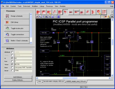
As you can see there are three control panels as well as the menu and main schematic screen.
Common actions (large buttons)

The top panel contains large buttons which display the most used controls (below this are smaller buttons for less frequently used operations e.g. text size, color control etc).
Note: You can access all the tools using the buttons or hotkeys e.g. Alt-w Wire tool,Alt-s Select tool and you can see each hot key by opening the Tools menu.
Draw a schematic using four main buttons.
All you need are:- Library part selector/manager. (The 3-books symbol).
- Select tool. (The arrow).
- Wire draw tool. (The line with 'wire' text).
- No-connection - at a pin. (The X ).
Initiallly though these four are enough to draw schematics.
- Select a part using the library part selector..
- Place the part (click left).
- Stop part placement (click right or hot escape key).
- Use the wire draw tool to draw wires between pins.
- Use the no-connection to set pins as unconnected.
- Use the select tool to move parts or wires around the schematic.
Note: 'no-connects' tell the netlister accept a pin that has no wire connection - just a useful way of ensuring that you think about every pin in the design as you have to put the 'nc' in manually.
Schematic drawing software : Proceses
On the top left is a process panel that gives easy access to the main processes that you need in drawing a schemaitc progressing from design to the final netlist.These include pin review, netlisting and BOM output (Bill Of Materials).
Schematic drawing software : Attributes
Beneath that is the attribute panel that shows all the data for the currently selected part - this can include your own data e.g. manufacturer data etc.Attributes are pieces of data associated with a part - some are internal data such as the part information (for a multi part symbol) but you can add your own data such as Manufacturer, cost - any data you like.
Note: The BOM (Bill Of Materials - shopping list!) generator is customizable so you can output this data to a spreadsheet.
Schematic drawing software : Libary
The library has many different parts pre-made but if a part does not exist then its easy to create a new one as the library editor uses the same interface as the schematic tool - except for one control - the pin control.All you do is start the library editor and fill in a few bits of information (e.g. symbol name, symbol prefix, number of parts in the symbol etc. then on to the library editor. Just draw your symbol and add pins to it with the pin tool then click OK - and add to the library - and its done ready for use.
Schematic drawing software : PCB
Schematic drawing software : Layers
An unusual feature of this tool is that it has layers and these allow you to create complex diagrams that have detailed backgrounds. This type of feature is more usually found on graphics programs.Note that as well as adding backgrounds to a complete image you can add colored backgrounds to individual schematic blocks e.g. for an IC part (this background can be grouped with the part to keep background and part together).
Here's an example of a diagram created with the layer functionality:

The solderless bread board is on layer 6 while everyting else is on layer 1 so you can move all items on layer 1 without selecting anything on layer 6. It's just as if there was a fixed image in the background.
Download schematic drawing software FREE Trial here
Sign up for MicroZine (the free microcontroller ezine) and you can get the schematics from this site - in ProSchematic format : this gives you a head start in creating your own schematics.
End of schematic drawing software page.
Jump from schematic drawing software to
Best Microcontroller Projects Home Page.
Site Map | Terms of Use


Comments
Have your say about what you just read! Leave me a comment in the box below.
Don’t see the comments box? Log in to your Facebook account, give Facebook consent, then return to this page and refresh it.